Today’s world is full of electronic products and electrical devices that are susceptible to damage from overvoltage surges
Surges caused by static discharge, capacitive and inductive loads or lightning can quickly destroy sophisticated electronic equipment and components used in industrial and commercial applications. These surges cripple operations – particularly the data and communication systems that virtually every enterprise relies upon today,
18th Edition Surge Protection Requirements
Whereas the 17th Edition worked on the basis of the likelihood of a lightning strike - the principal cause of electricity surges - following the AQ criteria, BS7671:2018 instead considers the consequences of a strike and associated surge. Namely, regulation 443.4 states that an SPD must be installed where consequences caused by overvoltage include:
•‘Serious injury to, or loss of, human life’
•‘Interruption of public services and/or damage to cultural heritage’
•‘Interruption of commercial or industrial activity’
•‘Affecting a large number of collocated individuals’
This effectively means that everything but small domestic dwellings must now have adequate surge protection.
Causes and Consequences of Electrical Surges
Most electricity surges are caused either by lightning strikes or electricity switching. A bolt of lightning can carry a current of 200,000A and is particularly dangerous as the flashover can cause fire or electric shock. Switching surges caused by shutting down large inductive loads tend to be less extreme but more repetitive, potentially limiting the operating life of system components.
• Lightning strikes — Large scale impact, high current and voltage, but least common occurrence.
• Power switching — Increasing occurrences:
1.Utility and customer load switching – Motors, large loads, faults, capacitor banks, fuse and circuit breaker operation, etc.
2.Source switching — smart grid, gensets, photovoltaic power systems and wind power generation, etc.
In terms of SPDs, they serve to prevent damage to all parts of an electrical installation and attached appliances. This is caused by transient overvoltage exceeding the rated withstand limit of electrical equipment, thus causing damage such as burned components, degraded insulation and even melted wires.
Types of Surge Protection Device
There are three principal types of surge protection device in common use, depending on where they are installed within an installation.
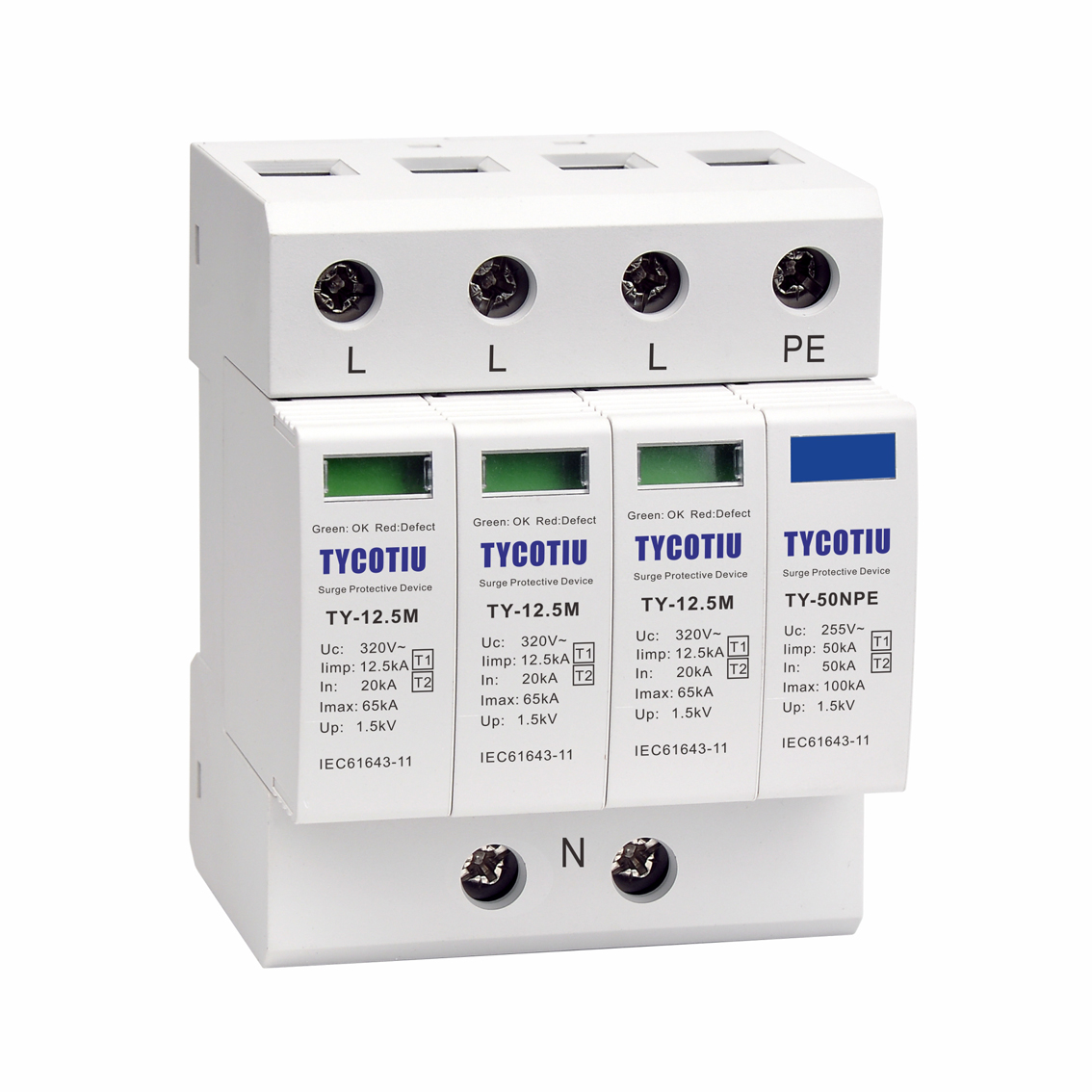
Firstly, Type 1 SPDs are capable of discharging partial lightning current with a waveform of 10/350µs. This makes them suitable for installation on the supply side of the main service entrance, protecting the whole installation including the service panel from overvoltage. Typically, they use a spark gap to direct the surge to earth and prevent it reaching the building.
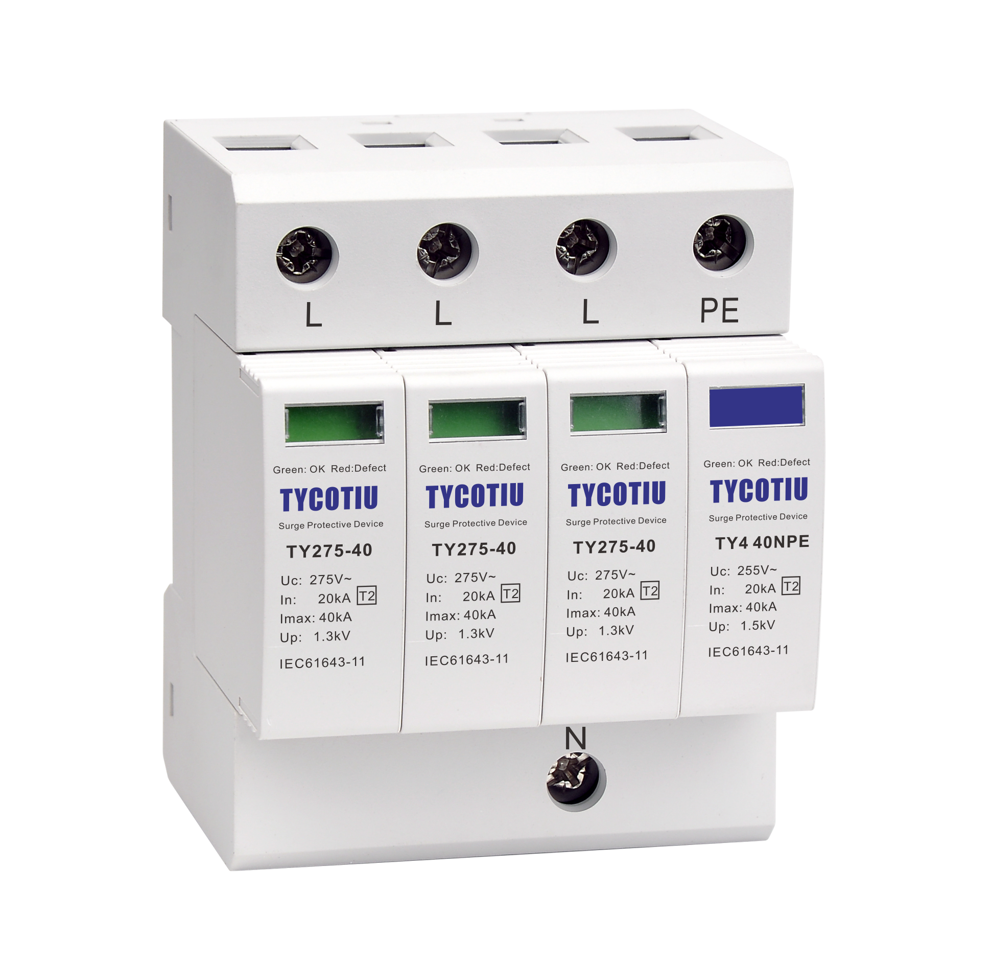
Secondly, Type 2 SPDs are intended to protect equipment attached to an installation. They are positioned on the load side of the main service entrance across phase-neutral or phase-phase and prevent the spread of overvoltage through a metal oxide varistor (MOV) with an 8/20µs current wave. MOVs maintain very high resistance until surge voltage is encountered, at which point resistance drops dramatically and excess current can be channeled to earth.
Finally, Type 3 SPDs are much smaller scale and should only be used in conjunction with a Type 2 device. They are specifically designed for protecting sensitive equipment such as televisions and computers from overvoltage. Their voltage waves tend to be around 1.5/50µs and current waves tend to be around 8/20µs.
Selection and Application of AC Power System SPD
Having determined the Class of SPD required, the correct voltage and configuration needs to be determined.
TN-C System
In this system, the neutral and protective earth conductor is combined in a single conductor throughout the system. This conductor is referred to as a PEN, a “Protective Earth & Neutral”. All exposed conductive equipment parts are connected to the PEN.
TN-S System
In this system, a separate neutral and protective earth conductor is run throughout. The Protective Earth (PE) conductor is normally a separate conductor, but can also be the metallic sheath of the power cable. All exposed conductive equipment parts are connected to the PE conductor.
TN-C-S System
In this system, the supply is configured as per TN-C, while the downstream installation is configured as per TN-S. The combined PEN conductor typically occurs between the substation and the entry point into the building, and earth and neutral are separated in the Main Distribution Board. This system is also known as Protective Multiple Earthing (PME) or Multiple Earthed Neutral (MEN). The supply PEN conductor is earthed at a number of points throughout the network and generally as close to the consumer’s point- of-entry as possible.
TT SYSTEM
A system having one point of the source of energy earthed and the exposed conductive parts of the installation connected to independent earthed electrodes. The incoming supply neutral is not earthed at the main distribution board.
In the TT system, in order for overcurrent protective devices (fuses and circuit breakers) to operate in the intended manner, it is important that SPDs must not connect directly from phase to protective ground, but from phase to neutral and neutral to ground. Therefore, the Neutral-to-PE SPD carries both the PE to neutral impulse current and the PE to phase impulse currents. This SPD is recommended to be a GDT (Gas Discharge Tube) due to their generally superior energy handling characteristics.
IT SYSTEM
A system have no direct connection between live parts and earth, but all exposed conductive parts of the installation being connected to independent earthed electrodes. The source is either floating or earthed through a high impedance (to limit fault currents). This means that during a Phase to Earth fault, the systems continues to operate. This is detected, and maintenance efforts commenced to rectify the fault. However, during this time, the Phase to Earth voltage rises to the usual Line to Line voltage, and installed SPDs must withstand this during this time. Most installed IT systems do not utilize a neutral conductor – equipment is powered from line to line. The IT system is typically used in older installations in countries such as Norway and France. It is also used in special applications, such as intensive care wards of hospitals and special industrial applications.
Coordination of Surge Protection
SPDs should have a protection level significantly lower than the rated impulse withstand voltage. SPDs should also always be from the same manufacturer.
An important factor to consider when installing surge protection is the total length of the leads connecting the SPD to the installation. They should be as short as possible, preferably totaling less than 0.5m and in no case totaling more than 1m. SPDs should always be installed according to the manufacturer’s instructions and preferably on the supply side of RCDs.