Indirect lightning strikes are destructive. Anecdotal observations about lightning activity are usually a poor indicator of the level of lightning-induced overvoltage in PV arrays. Indirect lightning strikes can easily damage the sensitive components within PV equipment, which often has a high cost to repair or replace the damaged components, and affects the PV system’s reliability. The overvoltage depends on the setup conditions of each PV system and the wirings.
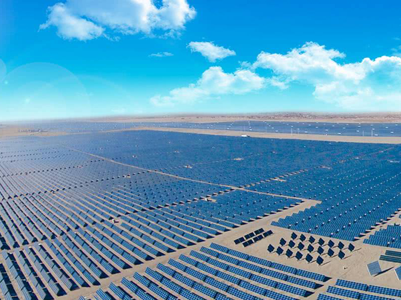
PV systems are exposed in large open spaces, typically in fields or on the tops of buildings. Charged rain clouds that accumulate over such open fields have the propensity to release the charge in the form of lightning. When this happens, a voltage surge is likely to occur. The more expansive the field is the more likely destruction is to occur.
When a PV system is located on an industrial site, the business operations and equipment are also at jeopardy. Inverters are expensive, but for industrial applications, an even more expensive failure is the cost of downtime.
When lightning strikes a solar PV system, it causes an induced transient current and voltage within the solar PV system wire loops. These transient currents and voltages will appear at the equipment terminals and likely cause insulation and dielectric failures within the solar PV electrical and electronics components such as the PV panels, the inverter, control and communications equipment, as well as devices in the building installation. The array box, the inverter, and the MPPT (maximum power point tracker) device have the highest points of failure.
To prevent high energy from passing through electronics and causing high voltage damage to the PV system, voltage surges must have a path to ground. To do this, all conductive surfaces should be directly grounded and all wiring that enters and exits the system (such as Ethernet cables and ac mains) be coupled to ground through an SPD.
A surge protection device is needed for each group of the strings within the array box, the recombiner box, as well as the dc disconnect.
Surge Protection Device Selection and Installation for PV Systems
PV systems have unique characteristics, which therefore require the use of SPDs that are specifically designed for PV systems.
PV systems have high dc system voltages up to 1500 volts. Their maximum power point operates at only a few percentiles below the system’s short circuit current.
To determine the proper SPD module for the PV system and its installation, you must know:
The lightning round flash density;
The system’s operating temperature;
The system’s voltage;
The system’s short circuit current rating;
The level of waveform that is to be protected against (indirect or direct lightning);
The nominal discharge current.
The SPD requirements for an installation that is protected by an external lightning protection system (LPS) depend on the selected class of the LPS and whether the separation distance between the LPS and the PV installation is isolated or non-isolated. IEC 62305-3 details the separation distance requirements for an external LPS.
To have a protective effect, an SPD’s voltage protection level (Up) should be 20 % lower than the dielectric strength of the system’s terminal equipment.
It is important to use an SPD with a short circuit withstand current greater than the short circuit current of the solar array string that the SPD is connected to. The SPD that is provided on the dc output must have a dc MCOV equal to or greater than the maximum photovoltaic system voltage of the panel.
SPDs for the Dc Side of Photovoltaic Systems
PV sources have very different current and voltage characteristics than traditional dc sources: they have a non-linear characteristic and cause long-term persistence of ignited arcs. Therefore, PV current sources not only require larger PV switches and PV fuses, but also a disconnector for the surge protective device which is adapted to this unique nature and capable of coping with PV currents.
SPDs installed on the dc side must always be specifically designed for dc applications. The use of an SPD on the incorrect ac or dc side is hazardous under fault conditions.
Installation
SPDs should always be installed upstream of the devices they are going to protect. NFPA 780 12.4.2.1 says that surge protection shall be provided on the dc output of the solar panel from positive to ground and negative to ground, at the combiner and recombiner box for multiple solar panels, and at the ac output of the inverter.
The proper installation of an SPD relies on three values, which are:
Maximum continuous operating voltage: The voltage that the SPD will activate.
Voltage protection level: The equipment’s overvoltage category must be higher than the SPD’s voltage protection level.
Nominal discharge current: The peak value of waveform (8/20 μs for type 2 SPDs) that the SPD is capable of withstanding after repetitive surges.
How to Combine SPDs with Inverters
PV farms are comprised of very sensitive equipment that needs expansive protection. Because PV farms create direct current (dc) power, inverters (which are necessary to convert this power from dc to ac) are an essential component to their electrical production. Unfortunately, inverters are not only highly susceptible to lightning strikes but they are incredibly expensive.
NFPA 780 12.4.2.3 requires additional SPDs at the dc input of the inverter if the system inverter is more than 30 meters from the closest combiner or recombiner box.
Install the SPD between the fuses and the inverter if there are string protectors (such as fuses, dc breakers or string diodes)
To connect an SPD when there is an inverter with an integrated fuse box, ensure that the internal fuses are bypassed and that the external string fuses are connected.
String inverters should be installed as close to the strings as possible. SPD cables that connect to the L+/L- network, and between the SPD’s terminal block and ground busbar, must be less than 2.5 meters. The shorter the connection cables, the more efficient and cost-effective the protection will be.
For inverters with only one MPP tracker, combine the string before the inverter and connect them to the SPD at the point of interconnection.
SPD combinations should be planned for each input when the inverter has multiple MPP trackers. An SPD must be used for each input that is fused with a string diode.
References
[1] Lightning Protection Guide, DIN EN Standard 62305 - 3, 2014.
[2] Standard for Surge Protective Devices, UL 1449, 2014.
[3] Low-voltage surge protective devices - Part 32: Surge protective devices connected to the d.c. side of photovoltaic installations - Selection and application principles, IEC Standard 61643-32, 2 017.